<< Start with Manual Transfer Switch Installation: Part 1
Connecting the Main Utility Supply
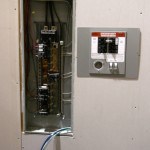
Route the two colored hot wires neatly through the transfer switch box to the utility supply breaker and trim them to length. Strip the insulation back 1/2 inch from the wire ends and insert them into the lugs. Tighten the lug screws firmly.
Route the white neutral wire to the neutral bus. Trim the wire to length, strip the end and connect it to the bus.
Note: Switched Neutral Installation only: Route the white neutral wire to the utility supply breaker in the transfer switch. Trim the wire to length, strip the end and connect the wire to the neutral lug on the utility supply breaker.
Route the green ground wire to the ground bus, trim and strip it, and connect it to the ground bus.
Portable Generator Safety Rules To Live By
Connecting the Branch Circuits
For each circuit that will receive generator power, disconnect the wire from the circuit breaker in the main service panel. Strip the end of the wire to 3/4 inches and twist the bare end together with a new length of the same gauge and color wire using a lineman’s pliers. Complete the connection by twisting on a wire nut.
Feed the new wires through the conduit to the transfer switch and connect them to the matching breaker in the manual transfer switch. Route the wires neatly.
Buyer Guide: What Size Generator Do I Need?
The transfer switch ground wire that connects to the main distribution panel’s ground bus will use the home’s existing grounding electrode to ground all the electrical circuits and also connect the generator’s equipment ground to the home’s grounding electrode. It is unnecessary to move the ground wires to the transfer switch ground bus.
Switched Neutral Installation only: Locate the white neutral wire for each branch circuit and disconnect it from the neutral bus in the main panel. Extend the wire through the conduit and attach it to the neutral bus in the manual transfer switch.
How to Use a Portable Generator During a Power Outage
Connecting the Inlet Box
Pull the four generator supply wires through the conduit from the inlet box to the manual transfer switch. In the transfer switch, route the two hot wires to the generator breaker. Trim and strip the wires and attach them to the breaker lugs.
Route the ground wire to the ground bus and attach it. Attach the white neutral wire to the neutral bus.
Note: Switched Neutral Installation only: Route the white neutral wire to the generator supply breaker in the transfer switch. Trim the wire to length, strip the end and connect the wire to the neutral lug on the utility supply breaker.
Make connections in the inlet box. Do not trim the wires too short. Leave some working room—each wire should be at least 8 inches long inside the inlet box. The two colored hot wires connect to the receptacle terminals labeled “X” and “Y”. The ground wire connects to the “G” terminal and the neutral wire connects to the “W” terminal.
Finishing the Installation
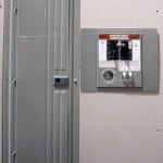
Replace the cover on the main service panel. Write the name of each circuit on the transfer switch circuit list for future reference. Replace the manual transfer switch cover, and the inlet box cover.
Turn the transfer switch circuit breaker to the “OFF” position in the main distribution panel. Leave any circuit breakers no longer used in the “OFF” Position.
Move the transfer switch to utility supply. Check to ensure the generator breaker is “OFF” and the utility breaker is in the “ON” position.
Turn on the main breaker and test your circuits. All should be functioning as normal.
Portable Generator Sizing Guide
Turn the main circuit breaker off. Position your generator outside and start it. Connect it to the inlet box with the power cord. Move the manual transfer switch to generator power. All circuits should operate normally off of generator power.
Return the transfer switch to utility supply. Turn off your generator and disconnect it.
You are ready to call for your final electrical inspection.
Always Consult a Licensed Electrician Before Starting Any Electrical Work On Your Home
Norwall PowerSystems
Updated October 2, 2020


