

Installing a manual transfer switch requires planning, a step you should not skip. After you obtain a building permit and know your plan is approved, you can move forward with your installation. The plan you presented to the building department included your materials list and you should not make any substitutions until you call and obtain approval for different materials.
The building permit and inspection serve as additional insurance. If a fire were to damage your home, an unauthorized and non-inspected electrical modification could void your home’s insurance policy. A passed inspection tells the insurance company and prospective home buyers that the job was done right.
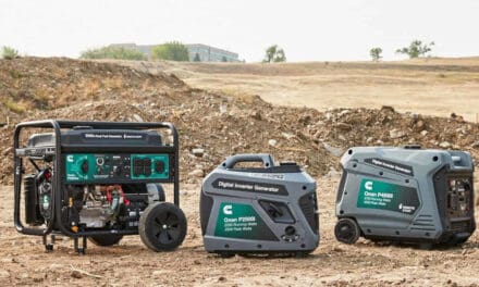
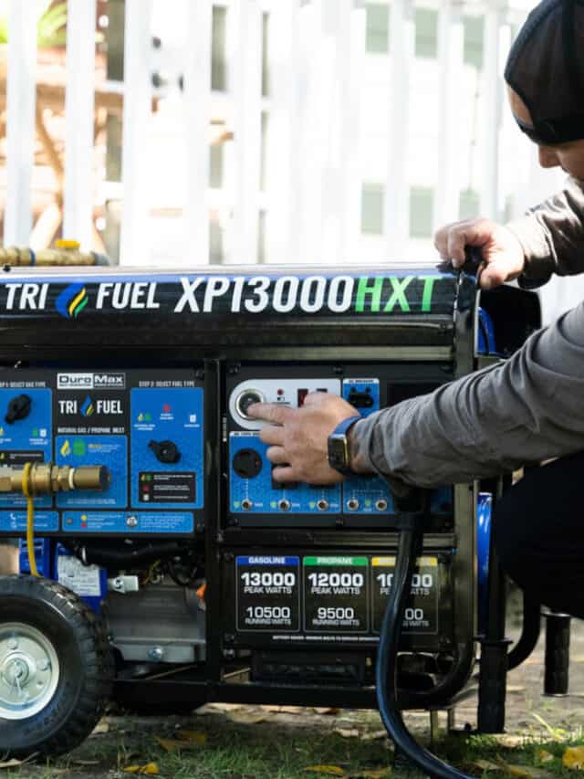
Portable Generator vs Standby Generator—What You Should Know
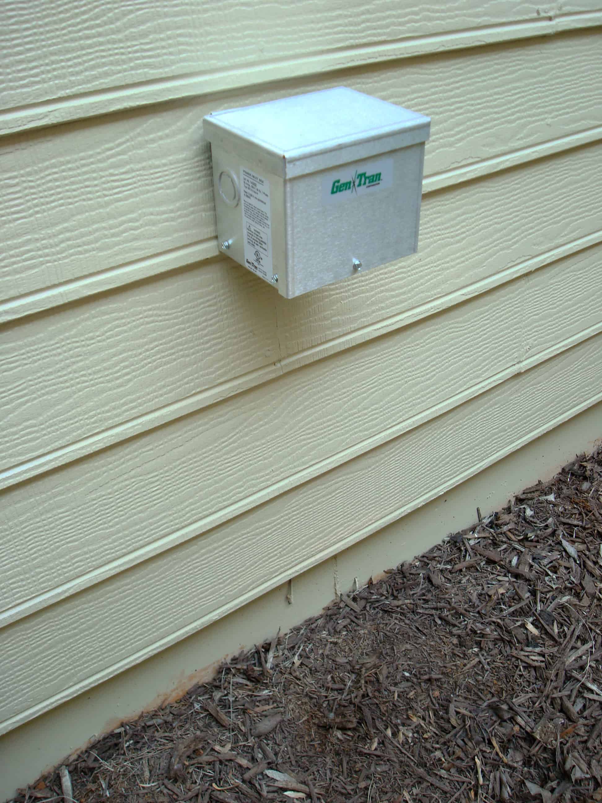
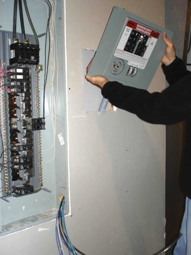
Install the Inlet Box and Transfer Switch
Mount the inlet box in the location chosen while planning the installation and detailed on your permit application drawings. Place the box against the wall, level it with a torpedo level, and mark the mounting hole and cable/conduit locations with a pencil. Drill pilot holes for the screws and the PVC conduit, add some caulk to each hole to seal it, and screw the box to the wall.
Place the transfer switch against the wall on either the left or right side of the main distribution panel as planned. Level the transfer switch with a torpedo level and drill pilot holes for the screws. Screw the manual transfer switch to the wall. Caulk is not required indoors.
Run PVC conduit between the inlet box and the transfer switch. Connect the conduit to the inlet box and transfer switch with watertight connectors. Each length of conduit comes with a bell shaped end for easy connections, or you can make connections using PVC conduit connectors.
In Stock Portable Generators For Sale Ship Fast
Note: Whenever the turns in the conduit exceed a total 360 degrees, an LB fitting or junction box is required.
Install PVC conduit support brackets every three feet for conduit sized 1 inch or smaller, and every five feet for 1 1/4-inch to 2-inch diameter conduit.
Connect the manual transfer switch to the main circuit breaker panel with PVC conduit and fittings. Connecting the conduit to the load center will require removal of the front panel and a knockout―turn off the main breaker or main disconnect first.
Warning: Always turn off the main circuit breaker before removing the front panel on the service panel. The large lugs that connect the main circuit breaker to the utility wires are always live and cannot be shut off in most circumstances. Do not touch the utility wires or the lugs on the main circuit breaker for any reason.
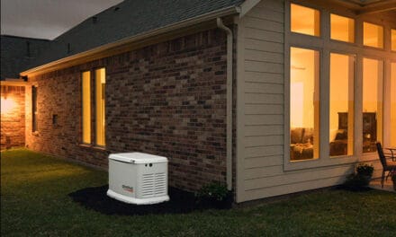
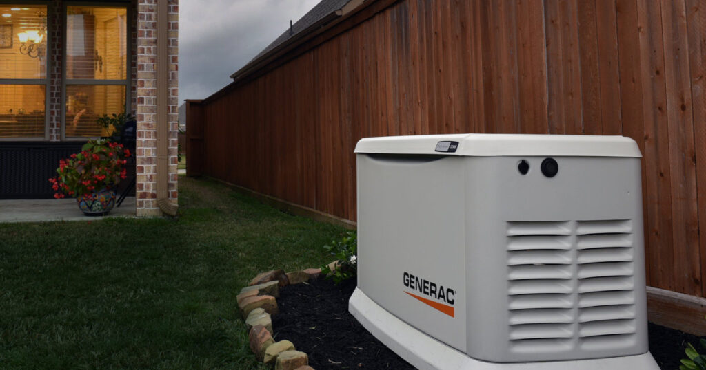
FEMA Recommends a Home Backup Generator for Emergencies
Connecting the Main Utility Supply
Locate the breakers that control the circuits the generator will supply during an outage and turn them off. Remove two breakers installed alongside each other from the service panel. The rest may remain in place unless you plan to use them in the transfer switch.
Install the new, 240-volt, double-pole breaker that will supply the manual transfer switch. Feed the four supply wires through the conduit to the manual transfer switch. Strip 1/2 inch of insulation from wire ends inside the main panel.
Pro Tip: Inspectors like neat work. It’s easy to follow and see there were no mistakes. Don’t skimp on wire. Arrange the wires to follow the same path as those already in the main panel. Do the same inside the manual transfer switch.
Pre-Wired Manual Transfer Switches Make Installation Fast and Easy
Route the wires neatly through the main service panel to their correct locations. Follow the conventions the original electrician used when wiring the box, and keep all the wires neat.
Loosen the lug screws on the new double-pole breaker and insert the ends of the two hot (colored) wires into the lugs. Tighten the lug screws firmly to the manufacturer’s specification. Connect the end of the white neutral wire into an empty space on the neutral bus bar―identified by the other white wires connected to it. The green ground wire attaches to the ground bus which has bare or green wires attached to it.
Note: NEC code requires bonding (electrically connecting) the white neutral bus to the ground bus in exactly one location. For this reason, many electricians use the same bus bar for both neutral and ground in the main service panel. Follow this convention only in the main service panel and only if it was already wired this way.
Continue with Manual Transfer Switch Installation: Part 2
*Always Consult a Licensed Electrician Before Doing Any Electrical Work on Your Home
Norwall PowerSystems
Updated October 2, 2020


