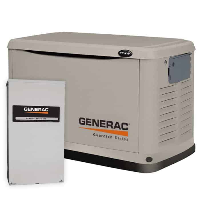
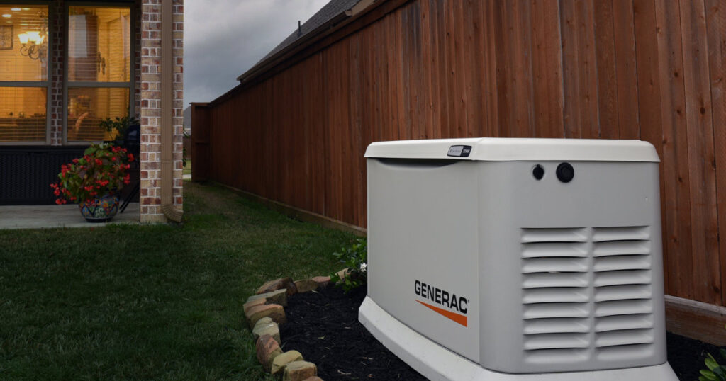
Smart Switch automatic transfer switches from Generac manage power for entire homes with the help of digital power management technology. Appliances such as air conditioners, electric water heaters, and well pumps draw high levels of current at 240 volts and can take a big bite out of the amount of power available from a standby generator. Generac’s Digital Power Management system allows these heavy users of electrical power to operate without overloading the generator.
Power Management Strategy
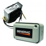
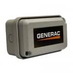
Generac Power Management Module PMM and Starter Kit 6199Note: The Starter Kit and PMM will only work with the RTSR and RTSY transfer switches.
Generac’s Digital Power Management strategy uses priority-based load shedding to control high-demand loads. Loads are assigned a priority from one (highest) to four (lowest) which are managed by the Overload Protection Control Board (OPCB) integrated within the automatic transfer switch.
The OPCB can manage two central air conditioning units without the addition of any hardware. Up to four additional loads can be controlled by adding Power Management Module Starter Kit (PMM), which requires the installation of a Power Management Module. The kit includes one PMM and the 24-volt transformer required to operate the modules.
When the generator’s voltage frequency drops below 58 hertz, the OPCB identifies the drop as an overload. Lower priority loads are turned off, lowering the demand on the generator and preventing the generator’s main circuit breaker from tripping or damage occurring to the generator caused by the overloaded condition.
Power Management Modules
Power Management Modules control 240-volt loads of up to 50 amperes by using an internal relay to turn the load on or off. The relay is an electric switch that uses minimal power to operate. PMMs connect to the control board LOAD terminals, which are numbered from one to four, corresponding directly to their priority assignment.
When the OPCB senses an overload, it sheds (turns off) the loads in order of priority from lowest to highest. An appliance connected to Load 4 is shed first, and Load 1 is shed last.
Power Management
The OPCB controls a typical air conditioner by switching the thermostat “Y” wire and assigns the first air conditioner as priority one, and the second air conditioner as priority two. The A/C terminal pairs on the control board may also control other devices such as heat pumps and two stage air conditioners, but will require the use of additional Power Management Modules and special wiring to do so.
Additional loads are managed through the load terminals on the OPCB. Each pair of load terminals connects to a separately purchased Power Management Module.
Loads 1 and 2 on the OPCB are assigned the same priority as A/C 1 and A/C 2 which allows those loads to run with the same priority as the air conditioners.
Power Management Configuration Examples
Example 1:
Two central air conditioners are connected to A/C 1 (priority 1) and A/C 2 (priority 2) on the control board. A hot water heater is connected to Load 3 and an electric dryer is connected to Load 4.
During an outage, the air conditioners get top priority. If the electric dryer and both air conditioners are running, and the hot water heater starts and causes an overload condition, the OPCB will shed the dryer load in favor of the hot water heater, because the hot water heater has a higher priority (3) than the electric dryer priority (4).
Example 2:
Two air conditioners are connected to A/C 1 and A/C 2, and a well pump is connected to Load 1. Load 1 is assigned priority 1, the same as A/C 1. If both A/C 1 and A/C 2 are running and the generator is operating near capacity, turning on the well pump may overload the generator.
In this case, the control board allows A/C 1 to continue running and allows the well pump to start and run because it has the same priority. A/C 2 is shut off because it has a lower priority than A/C 1 or Load 1. The well pump runs and fills the tank, then shuts off. A/C 2 is then allowed to start again.

